Introducing UML and UML Modelling Tools
UML Diagrams
UML is an acronym for Unified Modelling Language, This is a graphical representation of a system, the system components, and how the user interacts with the system.
Types of UML diagrams UML uses elements and associates them in different ways to form diagrams representing static or structural aspects of a system, and behavioral diagrams, which capture the dynamic aspects of a system.
Structural UML diagrams
Class Diagram: The most commonly used UML diagram, and the principal foundation of any object-oriented solution. Classes within a system, attributes and operations, and the relationship between each class. Classes are grouped together to create class diagrams when diagramming large systems.
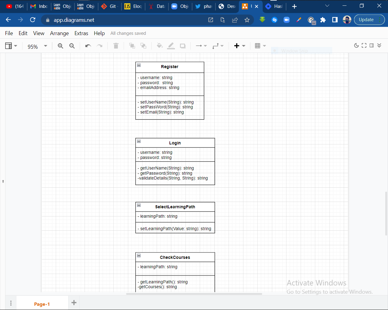
A simple example of a UML Diagram (Class Diagram)
Component Diagram: Displays the structural relationship of software system elements, most often employed when working with complex systems with multiple components. Components communicate using interfaces.
Composite Structure Diagram: Composite structure diagrams are used to show the internal structure of a class.
Deployment Diagram: Illustrates system hardware and its software. Useful when a software solution is deployed across multiple machines with unique configurations.
Object Diagram: Shows the relationship between objects using real-world examples and illustrates how a system will look at any given time. Because data is available within objects, it can be used to clarify relationships between objects.
Package Diagram: There are two special types of dependencies defined between packages: package import and package merge. Packages can represent the different levels of a system to reveal the architecture. Package dependencies can be marked to show the communication mechanism between levels.
Behavioral UML diagrams
Activity Diagrams Graphically represented business or operational workflows to show the activity of any part or component in the system. Activity diagrams are used as an alternative to State Machine diagrams.
Communication Diagram Similar to sequence diagrams, the focus is on messages passed between objects. The same information can be represented using a sequence diagram and different objects.
Interaction Overview Diagram There are seven types of interaction diagrams, and this diagram shows the sequence in which they act.
Sequence Diagram Shows how objects interact with each other and the order of occurrence. They represent interactions for a particular scenario. State Diagram Similar to activity diagrams, they describe the behavior of objects that behave in varying ways in their current state.
Timing Diagram Like Sequence Diagrams, the behavior of objects in a given time frame is represented. If there is a single object, the diagram is simple. With more than one object, interactions of objects are shown during that particular time frame.
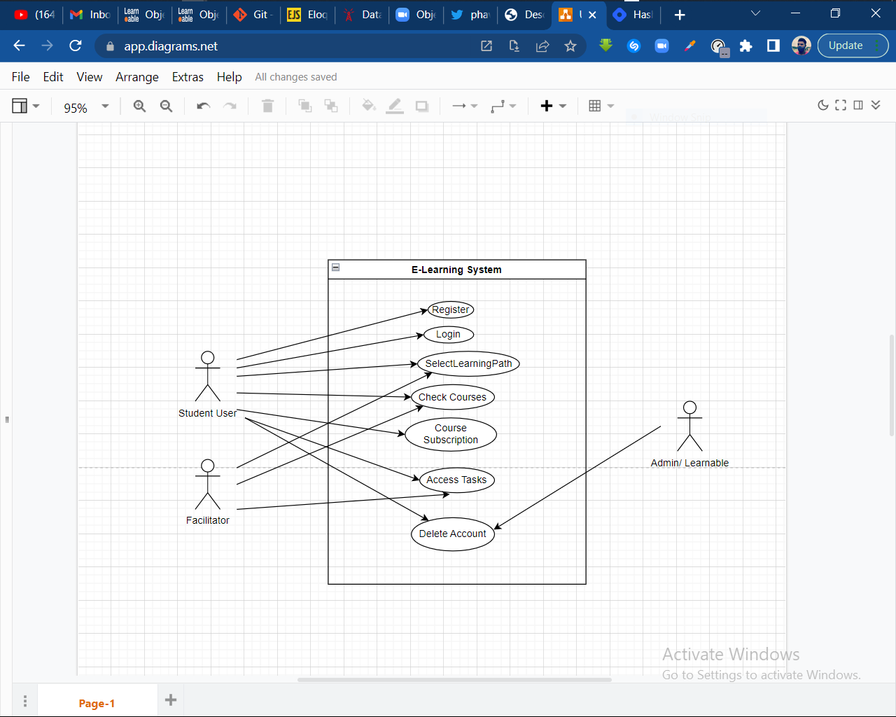
Use Case Diagram Represents a particular functionality of a system, created to illustrate how functionalities relate and their internal/external controllers (actors).
A simple example of a UML Diagram (Class Diagram)

